Posts

Putting sides and roof together
Image
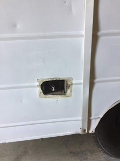
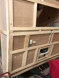
With the sides up and fastened to the floor, I added the front and rear cross pieces to connect them. After the front and rear cross bracing was installed, I adhered the interior birch paneling to them. In this photo, you can see the cutout for the original (well, original to me, but not original to the trailer) refrigerator venting. Since I need to match the cutout in the original aluminum siding which I am planning to reuse, I figured I would add a nice aluminum compartment door, whether it was functional or not. Since I couldn’t put a new gas operating fridge back in (I couldn’t find one small enough to fit the area safely) I decided on a nice 12volt/120volt unit which doesn’t need exterior venting. Also, on a random note, you can see how nice the use of a Kreg pocket hole screw jig is when building the trailer. I added the necessary support blanks within the framing for the future solid screw anchoring of  exterior light fixtures and other random vents, etc. These wer...

Building the sides

Image
Time to construct the sidewall framing. I put together the aluminum siding so that I could use it as a template. When I compared both sides of the assembled aluminum siding, I noticed that the sides didn’t match. Since I wanted to make two identical frames (the perimeter), I knew I would need to fudge the aluminum siding on one side to fit the frame when that time came. Drivers side  This is the inside of the passenger side skinned with 1/8” birch. I used a polyuerathane construction adhesive to glue the birch plywood to the frame. I used bricks as weights to keep pressure on the frame against the birch until the adhesive dried. Passenger side frame. I used exterior type 3 wood glue and pocket hole screws for the joints. The frames are made of 3/4” marine grade plywood. I copied the original frames for the most part. I did add some bonus pieces in select areas for strength or where a hole might be drilled or a fixture attached.

Down to the Frame

Image
Here you can see here the previous owner cut off the ends of the rotten stringers and added the cross piece between both frames. The cross piece is removed.  With the floor completely removed, it was easy to see the work that needed to be done to the frame. Some rust removal for sure, some straightening of bent supports, and some welding type of repairs. I noticed when pulling Otis to the shop that the trailer appeared to “bounce” or rock forward and backward. Once I got to this stage of the teardown, I realized why. The frame had two serious stress cracks in the wimpy c-channel where they were welded/attached to the front L-channel cross member support. It’s apparent that the weight of the body puts a lot of stress in this area. I would eventually repair this with an extra plate of steel in these areas. I would also weld some brackets in the areas of the leafspring eye supports the width of the c-channel, in a sense, boxing in those 4 areas. There were also ...

Some more random rot photos of Otis

Image

Let the real demo begin!

Image
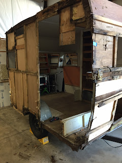
 After ripping out the kitchen counter assembly, I began tearing down sections of walls. It continues to be apparent that the structural integrity of Otis was gone long ago. With the entire passenger side and front dismantled, it was almost time for it all to come crashing down. The previous owner installed laminate flooring. It was pieced in pretty badly.  With all the walls torn down, the floor was next. The white plywood is in the rear where the last owner attempted to replace a rotten section. This photo also shows the cool galvanized fender wells removed. They were in great shape. 

A little roof action

Image
These two photos show how whimpy the roof is built for light weight reasons. One would never want to put their full body weight on it, that’s for sure. The upper picture shows the vent cut out. The trailer  came with a basic crank open non powered vent. I would replace it with a powered unit for nice air circulation. Both photos show how the high voltage line was simply just draped over the roof spars and the aluminum roof just set on top of it. I’m derstand it’s hard to rout wire through 3/4” thick material, but man, this just seams like a bad idea for many reasons. I would route the new wire inside the trailer cabinetry via conduit for a much more protected path and easier accessibility.

Entry Door

Image
 The door is in pretty good shape. I think it will clean up nicely. I would eventually figure out how to “beautify” the interior side. It’s wrapped in a textured aluminum painted a tan color that isn’t very nice looking.  I would replace the door screen with new aluminum screen and beading. The only minor defect with the door was the obvious damage left by someone trying to pry the door open. I look at that as history and will just let it be. The best part of the door is the original working door knob and lock. It’s a really nice piece of mechanical beauty that is unique in the way you twist the knob from the inside one direction in order to lock the door.

Bunk Window

Image
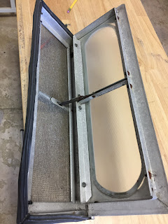
 I love the little bunk window! I look forward to rebuilding all the windows, but especially this little guy.   The screen looks in good shape.   It’s no surprise the seal is hard, shrunken and pulling away from the frame.

Water tank Fun

Image
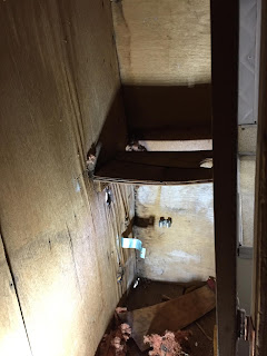
 This is the shelf that held the water tank within the closet area. I have not officially figured out the tank capacity, but I’m guessing it’s around 10 gallons. That’s a lot of weight on a single piece of 1/2” plywood! I will definetely beef this up in the rebuild. You can also see more water damage in the floor and wall corner area.  Here’s another picture but showing more of the upper portion of the area. Again, you can see in the upper corner, water entry, in its earlier stages. Here is the water tank. I will sanitize and re use it. It looks to be in good shape. I will obviously replace the copper and vinyl tubing. One of the problems I noticed with the installation of the tank on the shelf is that the tank does not have a flat bottom to sit on. Instead, it’s got extruded reinforcements that creat weird high spots that make the tank wobble around. I will remedy this later by building risers that will make the area around the reinforcements flush with the...

Exterior plumbing, electrical Inlet

Image
This is where the standard 15 amp Inlet is located. The simplicity of the original single outlet and one light fixture allowed only a 15 amp Inlet, but I will be adding an RV 30 amp Inlet in its place. This will allow me to install a 30 or 40 amp converter/power center. I have grand plans for the new electrical system that include lots of lighting, outlets, and various other goodies.  This is a close up of the sink drain, vent, and city water connection. I will do what I can to update the plumbing. Because I need to use the existing cutouts, I saw the need to probably add decorative aluminum plates to cover screw holes and then redrill access holes through them. This will become more clear when I talk about it later at that stage.  Here is a picture of the water tank filler spout. The water system is a gravity feed system. The really cool cast aluminum fill spout is installed a little higher than the top of the tank. I can’t wait to clean it up. The lit...

Dinette Action!

Image
 This is the passenger side of the dinette. The red grain plywood is some import stuff that looked awful. It was installed as an attempt to repair water damage on the rear of the trailer.   This shows the complete dinette. Kinda a mess.  This is the drivers side of the dinette.  The dinette converted into the bed. I had lots of ideas for this area. I wanted to possibly try and make the drivers side of the new bed wider. This would mean shortening the pantry a bit. I also don’t like the boards and stick supports needed for the bed. I wanted to construct something more efficient that simply slides in and out to support the seat cushions. 

Pantry and kitchen cabinets

Image
 The pantry and closet. That electrical box has to go! My plan would be to install a converter power center somewhere in the closet or pantry area.  The two above counter storage areas. You can also see the ceiling sagging around the roof vent. In this picture, I have already removed the nasty broken fridge as well as the drawers. As I tear down things on the inside, my brain can’t stop thinking about the location of future wire and plumbing runs. 

Plumbing and Stove

Image
 This is a picture of the water tank and drain/vent assembly. Take note of the wimpy 1/2” thick plywood shelf that holds the 10 gallon tank. My goal was to reuse this old school brass assembly.  In this picture, I already removed the drain pipe portion that attaches to the sink. I love knowing it’s one year older than I am! Here is the sink underside. Again, my goal was to cleanup the brass drain pipe an reuse it.  The sink and faucet. The sink was pretty banged up, but the faucet looked rebuildable. I can’t wait to completely update the stove area. Although really cool in a vintage way, the wall areas  just look so random and busy. The range hood was very rusty. Nothing I couldn’t refinish easily, but I was thinking I would like to add a fan and filter (updated range hood) As for the stove/oven, I’m also thinking I would just update in someway. 

Rot, Rot, and more Rot, OH MY!

Image
 Rear driver side roof corner  Passenger side damage. The tape was my attempt to hold together what was left for future measurements and/or template making in order to recreate new structure later. Again, this portion of structure was literally rotted away. Looking up at front driver’s side roof corner Front view. The bottom front portion was rotted away so much that the structure was sagging downwards. I see so much opportunity to bring Otis back to life with new materials!